


 |
| Here is a view of the disc brake setup. It is a mechanical system that uses a simple cable. |
 |
| We made the alternator adjustable to get the alignment correct for the front bearing. |
 |
| Actuator for the disc brake. |
 |
| It was decided to make the generator vertically adjustable so all the bearings can be aligned. |
 |
| Vice grips are an amazing tool that should be found in every tool box. |
 |
| Andrew Bache lining everything up. |
 |
| Andrew welding |
 |
| Chris M. welding. |
 |
| Andrew came up with the nice looking brake caliper mount. |

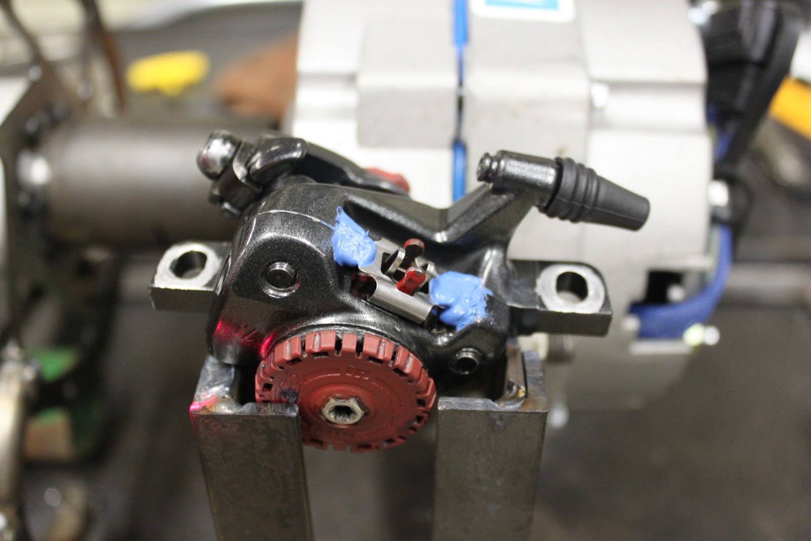 |
| A bit of silicone was dabbed on to keep the clip in place. |
 |
| Started with the brake hub we made earlier. |
 |
| The edge finder (which is .200" thick) allows you to see when it is just touching, then you raise it up, move over half the distance (.100"), and zero your axes. |
 |
| You can see the readout has been zeroed. |
 |
| Next you use the center drill and create a small hole in the material. |
 |
| Send your drill in. |
 |
| In this case we wanted to counter sink the bolt head so an endmill was sent in the depth of the screw head. |
 |
| Sits nice and flush so it is time to tap threads. |

 |
| Threads tapped. |
 |
| Opposing screws was a bad idea because it caused it to pivot about their contact points. |
 |
| Bryan Ennis explaining to Britt Christy what he is doing on the lathe. |
 |
| Weld preperation |
 |
| Brit getting the hang of welding |
 |
| After some practice she managed to create this textbook weld. |
 |
| This is how it started. |
 |
We used the main shaft to center the bearing.
|


 |
| Sam Haycox is doing all the leveling also taking into account that the welding table (and the ground for that matter) isn't level. |
 |
| John is getting thrown into the world of welding. |
 |
| Like a Boss |
 |
| Spencer is touching things up. |
 |
| John is preparing the cylinders that will hold the vane into place. |

 |
| The art of deburring only comes through experience. |
 |
| Hoop for back of the housing. |

 |
| Hoop for front of the housing. |
 |
| Sam melting metal |
 |
| Oh what a boss. |
 |
| This is the making of the aluminum hub which the blades attach too. |
 |
| We started out by drilling and tapping the center of the 2.5" aluminum stock. |
 |
| The bigger drill bits from OSH are Chinese made and don't really work that well which is why the threads don't look so sharp. |

 |
| The piece was then threaded onto a jig that came up through the rotory vice and centered to the vise. |
 |
| Then you use a "Center Drill" to start all the holes. |
 |
| Center Holes complete. |
 |
| The next step was sending in the appropriate drill size for the tap used to create the threads. |
 |
| Now we get to remove the excess material and make the flange used to bolt the hub down. |

 |
| Then the holes were tapped from both sides by hand. |

 |
| Finished product! |


This comment has been removed by a blog administrator.
ReplyDelete